
Case Studies
Why Did This Mature Inflatable Product Keep Leaking?
The product was already mature and in mass production. Its PVC material was relatively thick at 0.60 mm. Yet after consumers used the product for a period of time, repeated air-leakage complaints were occurring.
The customer had heard that COMCO operates an internal physical laboratory, so they sent two cartons of existing products to us for investigation.
The objective was not simply to determine whether a sample leaked. It was to understand why a product that appeared normal after production could become vulnerable after repeated use.
→
50-Cycle Test
→
Weld Measurement
→
Destructive Inspection
→
Root-Cause Analysis
→
Engineering Improvement
→
New Sample
→
Validation
→
Production Order
The Problem: A Mature Product with Repeated Leakage Complaints
This was not a new product still in early development. The customer already had an established product and an existing supply source. The concern appeared after the product had been used for some time: consumers were reporting air leakage.
A visual inspection alone could not explain the pattern. As detailed in our engineering guide on Why Inflatable Products Leak: How Factories Control Leakage Before Mass Production, slow leaks and stress-induced failures often originate from deeper structural interactions.
The product therefore needed to be evaluated as an interrelated system of PVC material formulation, high-frequency (HF) welded connections, internal I-beam construction, tooling geometry, welding conditions and load distribution during repeated dynamic use.
COMCO’s physical testing lab and QA engineering team began with repeated-use stress testing and then opened the product for internal destructive inspection.
How We Investigated the Problem
1. Repeated Inflation and Deflation Testing
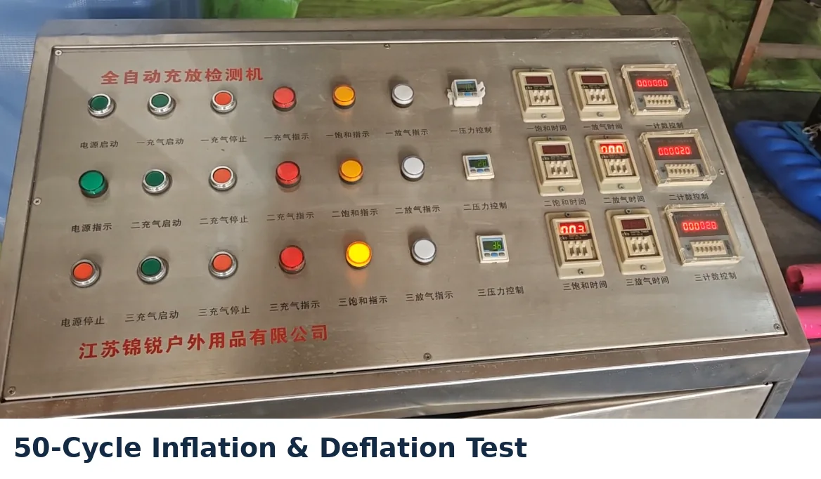
The samples were subjected to 50 inflation and deflation cycles as part of the initial investigation. The purpose was to introduce repeated inflation-related pressure and mechanical fatigue rather than relying only on a one-time static inflation check.
2. Weld and Material Measurement
The team inspected the welded seam areas and measured key dimensional parameters to understand how the PVC material had behaved under the compression, heat and dielectric energy of high-frequency welding.
3. Destructive Inspection
The product was then cut open under controlled laboratory conditions. This allowed the team to directly inspect internal areas that could not be evaluated from the exterior, including the internal I-beam connections, weld seam margins, and the physical condition of the welded PVC layers.
The investigation identified several interconnected risk points.
What We Found
Finding 1 — The Existing Welding Area Was Too Narrow for This Construction
The product used 0.60 mm PVC. Measurement of the existing welded connection showed a welding width of approximately 5 mm.
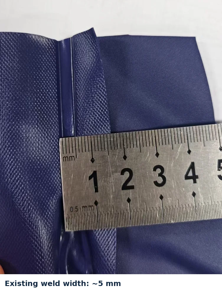
For this specific material gauge and construction, COMCO’s QA team considered the existing welding area insufficient for sustaining repeated internal dynamic loads, and recommended increasing the welding width to approximately 8 mm.
The important point is not that every product using 0.60 mm PVC should use an 8 mm welding width. The required welding area depends on the product structure, material formulation, loading conditions and manufacturing process.
Engineering takeaway: Material thickness and welding design cannot be evaluated independently. As explored in Does Thicker PVC Mean a Better Inflatable Product?, using thicker PVC does not automatically create a more durable product if the welded connection is not designed and processed appropriately for the structure.
Finding 2 — The I-Beam End Needed More Relief Space During HF Welding
The internal I-beam end incorporated relatively thick PVC layers in the welded connection. In the customer’s original construction, there were no relief holes in the I-beam end.
During high-frequency welding, PVC is rapidly heated and compressed under pneumatic pressure. In this case, the team identified a risk that excess softened PVC had insufficient space to redistribute and was being forced outward around the welded area, contributing to local material pinching and micro-damage.
COMCO proposed adding two relief holes to the I-beam end.
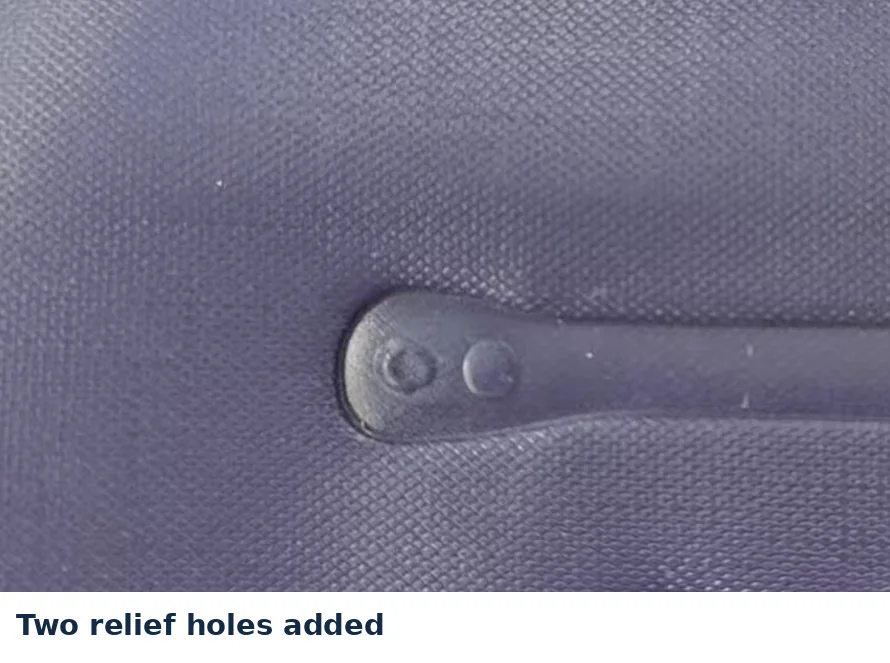
The holes provide dedicated volume for material displacement during the welding cycle rather than allowing softened material to be squeezed against the outer boundary of the joint.
Engineering takeaway: The issue was not simply the PVC thickness. How the material behaves under heat and pressure during the HF welding process is equally critical to long-term reliability.
Finding 3 — The Welded PVC Had Been Excessively Thinned
Another critical finding appeared after closer optical inspection of the welded area. A visible translucent zone indicated that the PVC around the joint had been heavily overheated and over-compressed during welding.
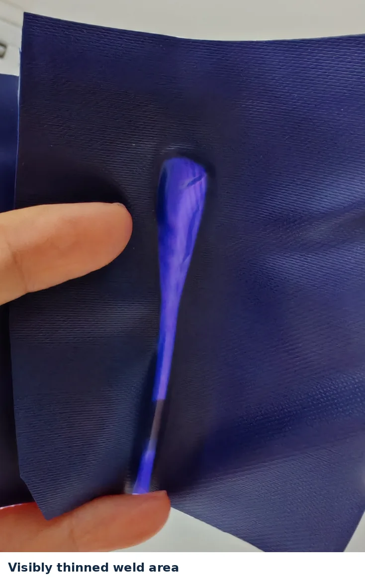
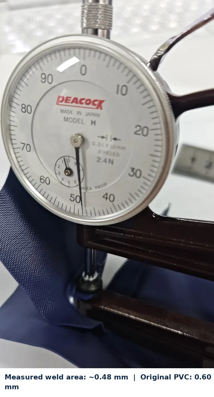
The team then measured the cross-sectional gauge of the welded PVC. The original PVC specification was approximately 0.60 mm, while the inspected welded area measured approximately 0.48 mm.
Together with the visual inspection, this supported COMCO’s concern that the HF welding parameters (energy, electrode pressure or dwell cycle) had been overly aggressive, causing severe local thinning and weakening of the PVC film.
COMCO recommended recalibrating the welding process under controlled electrical and pneumatic parameters so that a solid molecular fusion could be achieved without degrading the material structure.
Engineering takeaway: A welded connection should not be judged solely by whether it holds air immediately off the production station. The physical condition and retained gauge of the material after welding directly dictate how the connection performs under repeated consumer use.
Note on measurements: The approximately 0.48 mm measurement is an empirical observation from this specific investigation. It is not presented as a universal pass/fail threshold for all inflatable products.
Finding 4 — The I-Beam End Geometry Was Creating Excessive Stress
After cutting open the sample, the engineering team directly evaluated the internal I-beam geometry.
The original curved cut at the I-beam ends provided insufficient clearance for the structure to flex and distribute tensile loads smoothly during inflation and user movement. This created sharp stress concentration points directly adjacent to the welded connection under repeated load cycles.
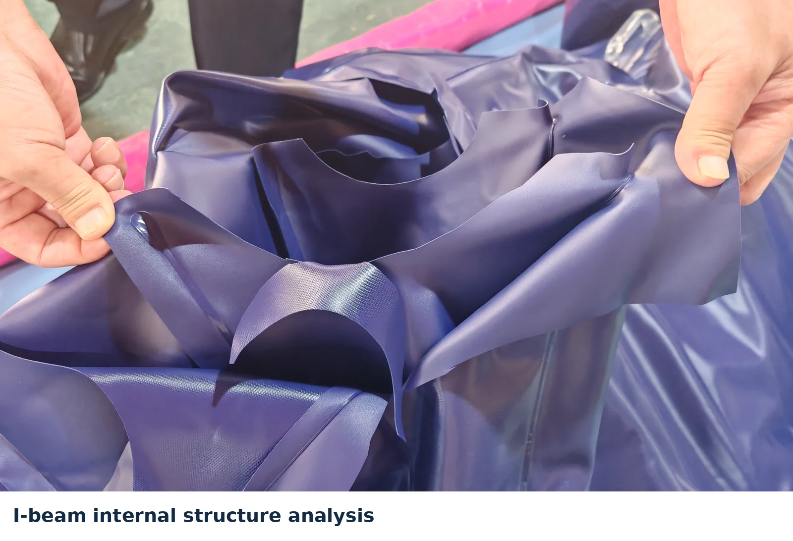
COMCO recommended enlarging the curved cut at the I-beam end to provide greater movement allowance and relieve localized stress around the welded connection.
Engineering takeaway: When repeated failures occur around a joint, the question is not simply “Where did it break?” It is “Why is the mechanical load concentrating here?” Answering that question transforms basic inspection into true root-cause engineering.
From Root Cause to Engineering Improvement
The investigation demonstrated how multiple interacting variables contributed to the customer’s leakage problem:
| Investigation Area | What We Observed | Engineering Direction |
|---|---|---|
| Material & Weld Design | 0.60 mm PVC with an approximately 5 mm existing weld width | Increase welding area to ~8 mm for this specific construction |
| I-Beam End Welding | No relief holes in the original I-beam end, causing material displacement pinch | Add two relief holes to allow material movement during HF welding |
| HF Welding Condition | Welded area visibly thinned and translucent; measured at ~0.48 mm | Recalibrate welding parameters to eliminate excessive local material thinning |
| Internal Structure | I-beam end geometry provided insufficient load-relief allowance | Enlarge the curved end cut to improve dynamic stress distribution |
Root-Cause Workflow: Repeated-Use Test → Measure → Cut Open → Inspect Internal Structure → Identify Root Causes → Modify Tooling / Structure / Process → Build New Sample → Validate
This is why leakage analysis cannot always be reduced to a single question such as: “Is the PVC thick enough?”
The performance of an inflatable product depends on how the material, welded connections, internal structure and manufacturing process work together.
What Happened Next?
COMCO presented the findings and proposed engineering improvements to the customer.
After reviewing the technical analysis internally, the customer placed a sample order based on the proposed changes. Following rigorous prototype validation, the project moved smoothly into a full production order.
The project did not begin with a request for COMCO to quote manufacturing. It began with an open technical challenge:
“Why is our existing product developing leakage problems after use?”
The ability to investigate that question thoroughly created the foundation for the next stage of cooperation.
What This Case Shows
A mature product in mass production can still contain hidden structural and processing weaknesses.
A relatively thick material does not automatically guarantee durability. A product that appears airtight immediately after leaving the welding line can still harbor vulnerabilities that only fail after repeated consumer use.
For inflatable products, reliable long-term performance depends on the deliberate interaction between:
Material + Tooling + HF Welding + Internal Structure + Stress Distribution + Validation
A manufacturer’s physical testing laboratory is therefore useful for far more than determining whether a production sample passes or fails a basic test. When testing is backed by deep manufacturing and tooling experience, it answers the question that matters most:
“Why is the product failing, and what specific engineering adjustments should be made before the next production run?”
Related Resources & Technical Guides
- Why Inflatable Products Leak: How Factories Control Leakage Before Mass Production
- Does Thicker PVC Mean a Better Inflatable Product?
- What Happens Before Mass Production? Pre-Production Quality Validation
- How Inflatable Products Are Made: From PVC Film to Finished Product
- From Sketch to Sample: How an OEM Inflatable Product Is Developed
- How to Choose an Inflatable Pool Manufacturer: A Buyer’s Guide
Related manufacturing capabilities: Product Engineering · Quality Control & Physical Lab · Prototyping & Sampling · Manufacturing
Have an Existing Inflatable Product with a Recurring Quality Problem?
If you already have a mature inflatable product but are experiencing repeated leakage, seam fatigue or structural deformation, the first step is rarely just increasing material thickness. The issue needs to be diagnosed in the context of the product’s internal construction and manufacturing process.
For a technical review, share your product type, existing material specifications, failure descriptions, photo/video evidence or sample availability. COMCO can review the information and determine whether laboratory analysis or development work can resolve the root cause.